Configuration
This equipment consists of the following components.
1) Spectratech OEG-17H Main unit ------------------------------------------------ 1-3 set
2) Spectratech OEG-17APD-00-D30 Sensor cable (Detector) ------------------------- 1 set / 1 unit
3) Spectratech OEG-17APD-00-E30 Sensor cable (Emitter) -------------------------- 1 set / 1 unit
4) Spectratech OEG-17APD-01-50 Light-blocking cap ------------------------------- 1 pc
5) Spectratech OEG-17APD-02 Optical phantom ------------------------------------- 1 set / 1 unit
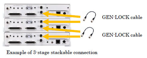
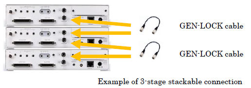
6) Spectratech OEG-17APD-06 GEN-LOCK cable -------------------------------------- 1-2 pc
7) Spectratech OEG-17H-07 CD-ROM for Application software ----==---------------- 1 pc
8) Spectratech OEG-16-05 BOX for manual event trigger input -------------------- 1 pc
9) AC adaptor TR60M05-26E13 CINCON -------------=-------------------------------- 1-3 pc
10) Operation manual ------------------------------------------------------------ 1 set
11) Spectratech OEG-17ME-06 LAN cable 0.5m×2 with isolator ---------------------- 1 set
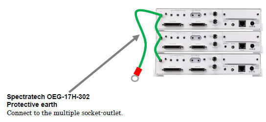
12) Spectratech OEG-17H-302 Protective earth 3.6m (2 or 3units) ------------------ 1 set
Sensor palette, PC, and Network HUB are not included. Please purchase separately.
※ The component beginning with Spectratech OEG-16- is in common with Spectratech OEG-16
※ The component beginning with Spectratech OEG-17APD- is in common with Spectratech OEG-17APD.
1) Spectratech OEG-17H Main unit -------------------------------------------------------------------------- 1-3 set
Front side of the main unit
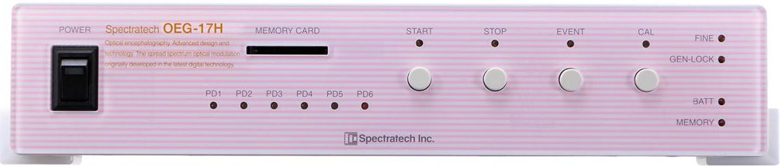
| POWER : | Pressing the upper part of this switch turns on the power supply and the LED lights up in green. |
|---|---|
| MEMORY CARD : | The accompanying SD memory card can be inserted, and support 4GB, 8GB, 16GB, and 32GB. This SD memory card is used to reset the IP address of OEG-17H when it was delivered or LAN connection was changed, etc. setting change in the payment time or the LAN access was done. (Resetting IP address is described in §2 of Software edition in detail.) |
| START : | Usually, a measurement/record is started by the command from PC not using this button. |
| STOP : | Pressing this button will stop a measurement/record. It is confirmed by the green LED lit up. It can be stopped also from PC. |
| EVENT : | This button is pressed when an event trigger is wanted to input manually from the front side of the main unit. It corresponds only during being measured. Another manual event trigger input is prepared also on the rear side of the main unit. |
| CAL : | This button is for the biological calibration, and not usually used because it is performed from PC usually. The LED is flashing in green during a calibration, and when it ended and all the channels have become in green (proper signals), it is possible to measure. The signal is not proper at some of the channels when it lights up in orange. However, a record can be begun. When it lights up in red, the signal is not proper at all the channels. When it lights up in orange or red, please confirm the mounting condition of the sensors to the living body, and try the calibration again. |
| FINE: | It lights up in green in FINE mode, and turns off in FAST mode. |
|---|---|
| GEN-LOCK: | It lights up when the OEG-17H is being synchronized with another OEG-17H as the master. |
| BATT-: | It lights up in red when the capacity of the internal button battery for the calendar clock fell less than the specified value. In such case, please replace it with a new battery soon. |
| MEMORY: | It lights up in red when the capacity of the SD-MEMROY fell less than 100MByte. |
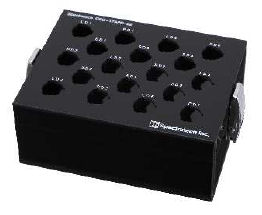
| PD1 - PD6: | It lights up in green when each biological signal input to PD1-PD6 is in the proper range. It lights up in orange to warn for an excessive input. When the sensor doesn't stick to the living body firmly, this phenomenon will come out in most of cases. You can measure as it is when it lights up in green as the calibration result described in §11. However, it lights up in orange, please reconfirm the mounting condition of the sensors to the living body, and use it in the condition of lighting up in green as much as possible. |
Back side of the main unit
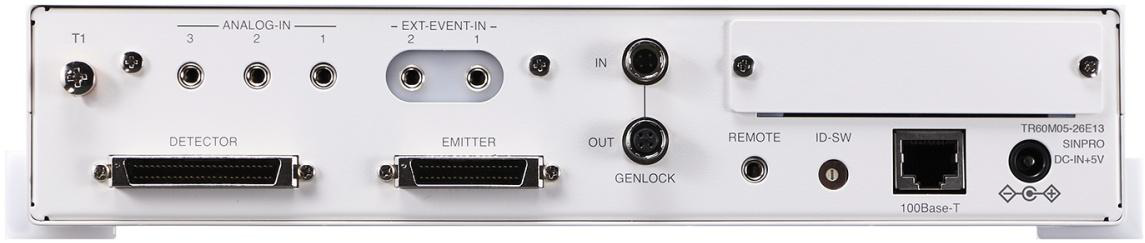
| DETECTOR: | The accompanying SpectratechOEG-17APD-00-D30 Sensor cable (DETECTOR) is connected. |
|---|---|
| EMITTER: | The accompanying SpectratechOEG-17APD-00-E30 Sensor cable (EMITTER) is connected. |
| EXT-EVENT-IN 1: | This is used as a measurement/record start input or an event trigger input from the outside via the optional SpectratechOEG-16-04 BNC cable for the external signal input. The button type battery for the photo isolation has to have been mounted to use this input. It is shipped with the battery mounted, and its lifetime is about 3-5 years. |
| EXT-EVENT-IN 2: | This is used as an event trigger input from the outside via the optional SpectratechOEG-16-04 BNC cable for the external signal input. The button type battery for the photo isolation has to have been mounted to use this input. It is shipped with the battery mounted, and its lifetime is about 3-5 years. |
| REMOTE: | Cable from the accompanying SpectratechOEG-16-05 BOX for manual event trigger input is connected. It is also possible to input an event trigger manually from the BOX. When an event trigger is accepted, the green LED on the BOX lights up. |
| ANALOG-IN1, 2, and 3: | This is the general-purpose analog signal input terminal, which can be measured simultaneously with the biological signal (hemoglobin change signal). It is convenient to measure simultaneously with sphygmograph and thermometer, etc. which has an analog signal output function. Input voltage range: 0 to +5V (High impedance input) Number of input channels: 3 Resolution: 12 Bit Sampling interval: Identical to the biological signal’s sampling interval (0.65535 or 0.08192 sec) |
| ID-SW: | This is used to identify this equipment in case of the stackable connection. The default value is 0. It will select the value of 1, 2, 3, ・ ・ ・ in order of the stackable connections. |
| 100Base-T: | This is used when it is connected to PC to monitor via wired 100M-ethernet. |
| DC-IN+5V: | DC output terminal from the accompanying AC adaptor TR60M05-26E13 CINCON is connected. |
| T1: | It is the terminal for connect to another OEG-17H for the stackable connection. In the case of 2 or 3 units, use T1 as a protective earth terminal. |
| GENLOCK-IN: | This terminal is used for the stackable connection of 2 or more OEG-17H main |
| GENLOCK-OUT: | units. The standard GEN-LOCK cable is used in case of the stackable connection.
|
2) Spectratech OEG-17APD-00-D30 Sensor cable (DETECTOR) ----------------------------------- 1 set / 1 unit
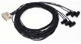 |
This is used by being attached to the various sensor palettes which are prepared to meet each region and sold separately. It is the sensitive sensor part which is mounted to the head together with the sensor palette, and acquires the biological information. It consists of the optical components which are made precisely, and very delicate. Please handle it carefully. The connector of this cable is connected to DETECTOR terminal on the back side of the OEG17H main unit. In addition, it is recommended to wipe up the oil and dirt on the sensor part with the rubbing alcohol before attaching it to the living body. |
3) Spectratech OEG-17APD-00-E30 Sensor cable (EMITTER) -------------------------------------- 1 set / 1 unit
|
This is used by being attached to the various sensor palettes which are prepared to meet each region and sold separately. It is the sensitive sensor part which is mounted to the head together with the sensor palette, and acquires the biological information. It consists of the optical components which are made precisely, and very delicate. Please handle it carefully. The connector of this cable is connected to EMITTER terminal on the back side of the OEG17H main unit. In addition, it is recommended to wipe up the oil and dirt on the sensor part with the rubbing alcohol before attaching it to the living body. |
4) Spectratech OEG-17APD-01-50 Light-blocking cap ------------------------------------------------ 1 pc
 |
Since the sensor of OEG-17H is ultrasensitive, the ambient light should be avoided. When the sensor palette was mounted to a subject completely, please be sure to start a measurement record after the subject’s head was covered by a light-blocking cap. |
5) Spectratech OEG-17APD-02 Optical phantom -------------------------------------------------------- 1 set / 1 unit
 |
This phantom is for confirming whether the light-emitting part and light-receiving part of each sensor operate normally. The detail is described in 3) Confirmation by phantom of §11 Calibration operation. |
6) Spectratech OEG-17APD-06 GEN-LOCK cable ------------------------------------------------------ 1-2 pc
7) Spectratech OEG-17H-07 CD-ROM for Installation software-------------------------------------- 1 pc
The content of this CD-ROM is installed on PC to operate the application software for this equipment. The usable PC has to have CPU Intel I5 or above, Main memory 8GB or above, Monitor in resolution of 1368 x 768, or above, and Network function (100M-ethernet), on which Windows 7, Windows 8, or Windows 10 is running.
8) Spectratech OEG-16-05 BOX for manual event trigger input (with 3m-long cable) ------- 1 pc
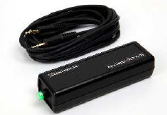 |
This BOX is assumed to be used for inputting a manual event input during a measurement/record from a position a little far from the main unit. The connector at the cable end of this BOX is connected to REMOTE terminal on the back side of the main unit. When the button on this BOX is pressed during a measurement/record, and it is input as an event trigger and acknowledged by this equipment, the LED on the button lights up to inform that. This BOX can be used also by being connected to EXT-EVENT-1 or -2. However, the LED on the button on this BOX does not perform the lighting-up operation. |
9) AC adaptor TR60M05-26E13 CINCON --------------------------------------------------------------------- 1-3 pc
It is connected to DC-IN on the back side of the main unit for the use.
10) Operation manual------------------------------------------------------------------------------------------------ 1 set
This is the operation manual for this equipment. The operation manual is also included in PDF format in the CD-ROM for Spectratech OEG-17H-07 Installation software.
11) Spectratech OEG-17ME-06 LAN cable 0.5m×2 with isolator -------------------------------------- 1set
12) Spectratech OEG-17H-302 Protective earth 3.6m (2 or 3units) ----------------------------------- 1 set
To prevent electric shock, be sure to connect Protective earth.
| To top of page |